
This is Part 2 in an on-going series of tutorials that will teach you how to build a Bussmann RTMR fuse/relay block for your vehicle. Part 1 was simply an introduction, but in this part I will get into the specifics of the parts needed to build this enclosure. There is a lot to cover with many specific details.
As a broad overview, here is a list of parts that you’ll need to buy. Some of these are self explanatory, yet others might be a bit foreign to you. As I detail each part, I’ll provide part numbers as well as where they can be sourced. Then at the end, I’ll reiterate with a complete itemized list of all the parts needed.
And as a reminder, I take no responsibility for damage, accidents, or injuries resulting from the fabrication or installation of any electrical modifications to your vehicle. You do so at your own risk.
Let’s begin with the Bussmann RTMR fuse block itself. What is it? Where can you get it? What differences are there between model numbers?
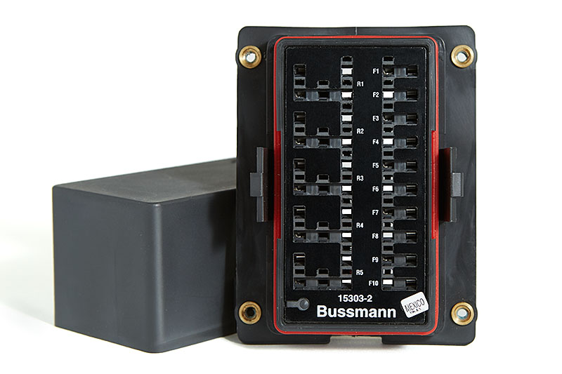
The Bussmann RTMR is made by Cooper Industries, and we will be using the Series 15300 RTMR. By looking at the datasheet for the box, you might quickly be overwhelmed with all the options. My hope is that I can simplify it for you. Let’s start with the Part Numbering System. Using the following table from the datasheet, we’ll be able to determine exactly what type of box to order.
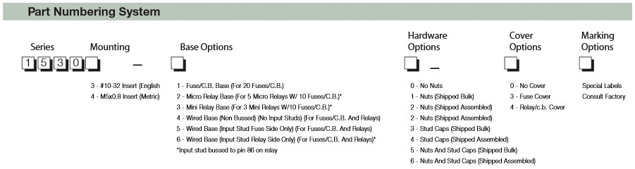
As an example, let’s use the model number, 15303-2-2-4, and decipher the values from left to right:
With the part numbering system in mind, study the Base Options in the following image from the datasheet in more detail.
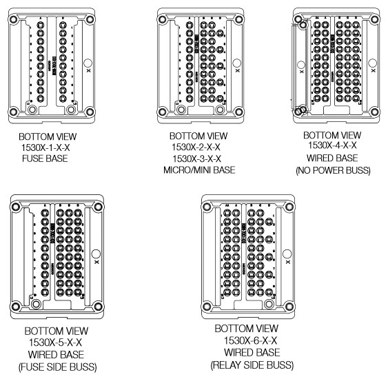
In my opinion, there are only two configurations that should really be considered for an auxiliary fuse/relay block. Having an internal bus for the fuses is very advantageous, because this allows a single power source to be connected to the RTMR that supplies power to each fuse. Therefore, our choices are limited to three configurations: 1530X-1-X-X, 1530X-2-X-X, and 1530X-5-X-X. Additionally, I want to be able to use relays in addition to fuses, so that eliminates 1530X-1-X-X from our three choices. Two remain, either of which will work, 1530X-2-X-X and 1530X-5-X-X.
There will be differences in how things are wired between these two versions, but this tutorial focuses on 15303-2-2-4. I’ll detail the connections in Part 4 – Wiring and Schematics.
Part used in this tutorial:
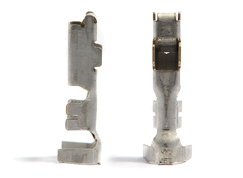
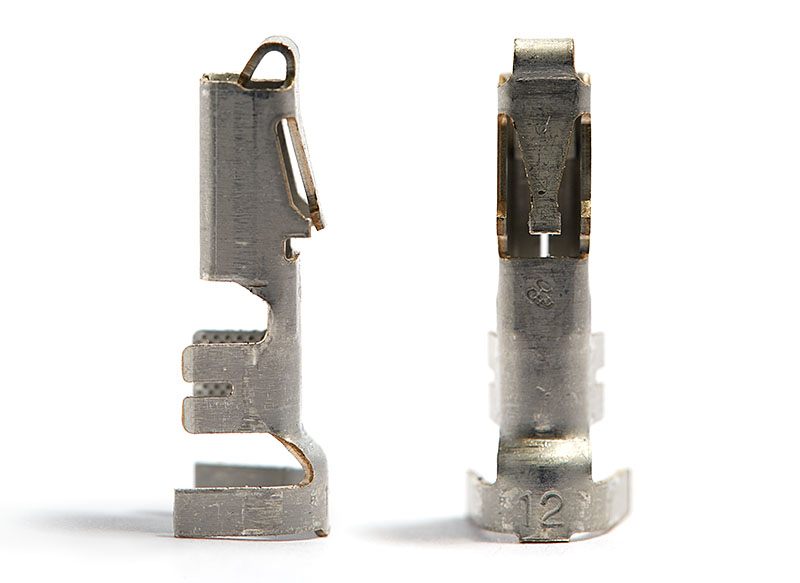
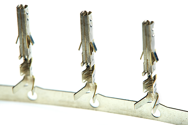
The Bussmann RTMR uses Metri-Pack 280 Series terminals and seals, which are made by Delphi Automotive PLC. There are two types of terminals offered in the Metri-Pack 280 Series, tanged and tangless. The RTMR specifically uses tangless sealed female terminals.
If you look at page 84 in the Metri-Pack catalog at Delphi, you’ll find a list of tangless female sealed terminals:
| Part # | Cable Range (mm2) | Typical Wire AWG Size | Material | Plating |
|---|---|---|---|---|
| 12110853 | 3.0-5.0 | 12-10 ga | Tin Brass | Tin |
| 12110845 | 2.0-3.0 | 14-12 ga | Tin Brass | Tin |
| 12129409 | 1.0-2.0 | 16-14 ga | Tin Brass | Tin |
| 12110847 | 0.80-1.0 | 18-16 ga | Tin Brass | Tin |
| 12110846 | 0.35-0.50 | 22-20 ga | Tin Brass | Tin |
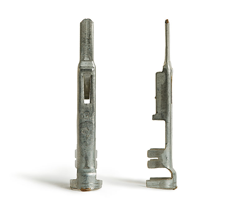
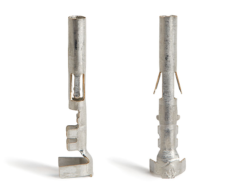
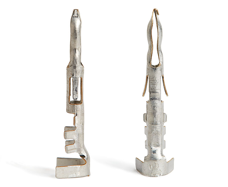
Later on, I’ll be using Metri-Pack connectors when making accessory cables that connect the Bussmann RTMR. These connectors, however, use tanged sealed female and male terminals. If you look at page 84 in the Metri-Pack catalog at Delphi, you’ll find a list of tanged female sealed terminals:
| Part # | Cable Range (mm2) | Typical Wire AWG Size | Material | Plating |
|---|---|---|---|---|
| 12077413 | 5.0 | 10-12 ga | Tin Brass | Tin |
| 12129493 | 3.0-2.0 | 12-14 ga | Tin Brass | Tin |
| 12077411 | 1.0-0.80 | 16-18 ga | Tin Brass | Tin |
| 12084201 | 0.50-0.35 | 20-22 ga | Tin Brass | Tin |
| 12176387 | 5.0 | 10-12 ga | Beryllium Copper | Silver/Nickel |
| 12176388 | 3.0-2.0 | 12-14 ga | Beryllium Copper | Silver/Nickel |
| 12176389 | 1.0-0.80 | 16-18 ga | Beryllium Copper | Silver/Nickel |
And then on page 85 in the Metri-Pack catalog at Delphi, you’ll find a list of tanged male sealed terminals.
| Part # | Cable Range (mm2) | Typical Wire AWG size | Material | Plating |
|---|---|---|---|---|
| 12048254 | 5.0 | 10-12 ga | Tin Brass | Tin |
| 12129497 | 3.0-2.0 | 12-14 ga | Tin Brass | Tin |
| 12048159 | 1.0-0.80 | 16-18 ga | Tin Brass | Tin |
| 12124977 | 0.50-0.35 | 20-22 ga | Tin Brass | Tin |
Parts used in this tutorial:
When making your parts purchase, you may want to buy terminals for other gauge sizes. These would be used in the Metri-Pack connectors for your accessories. Suggested parts to purchase would be:
I’ll be using a Weather-Pack connector for the switch wiring harness. These use different terminals than the Bussmann RTMR and Metri-Pack connectors.
Here is a list of Weather-Pack female terminals:
| Part # | Cable Range (mm2) | Typical Wire AWG Size | Material | Plating |
|---|---|---|---|---|
| 12124581 | 3.0 | 12-14 ga | Tin Brass | Tin |
| 12124580 | 2.0-1.0 | 16-14 ga | Tin Brass | Tin |
| 12089188 | 0.80-0.50 | 18-16 ga | Tin Brass | Tin |
| 12020801 | 0.35 | 22-20 ga | Tin Brass | Tin |
Here is a list of Weather-Pack male terminals:
| Part # | Cable Range (mm2) | Typical Wire AWG Size | Material | Plating |
|---|---|---|---|---|
| 12124587 | 3.0 | 14-12 ga | Tin Brass | Tin |
| 12124582 | 2.0-1.0 | 16-14 ga | Tin Brass | Tin |
| 12089040 | 0.80-0.50 | 18-16 ga | Tin Brass | Tin |
| 12089307 | 0.35 | 22-20 ga | Tin Brass | Tin |
Parts used in this tutorial:
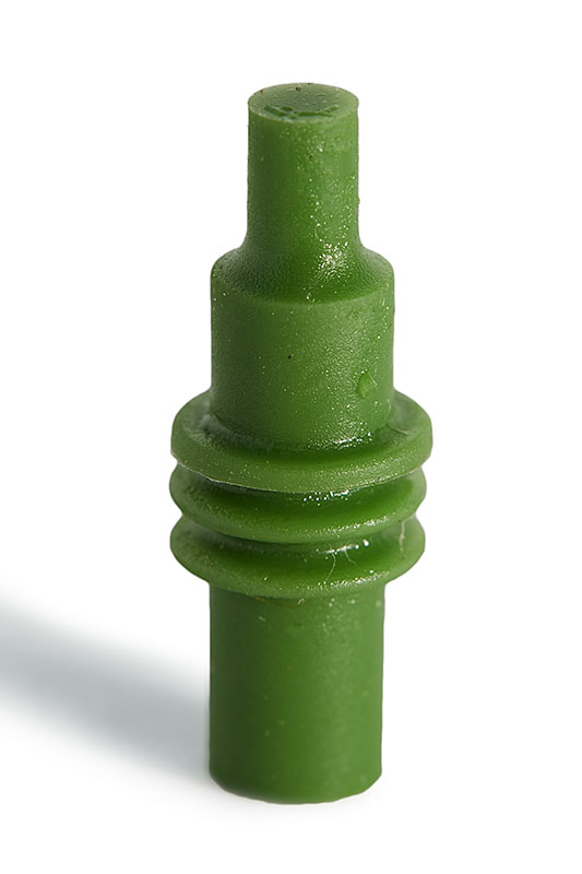
Within the Metri-Pack 280 Series of weatherproof connectors, the system works to keep the water and contaminants out of the electrical connection by using rubber wire seals. If you look at page 84 in the Metri-Pack catalog at Delphi, you’ll find a list of cable seals. Out of list, the Tan and Purple are not readily available so are not typically used.
| Part # (old / new) | Cable Diameter (mm) | Typical Wire AWG size | Material | Color |
|---|---|---|---|---|
| 12015193 / 15324981 | 4.30-3.45 | 12 ga | Silcone | Blue |
| 12010293 / 15324980 | 3.49-2.81 | 14-16 ga | Silcone | Lt. Gray |
| 12015323 / 15324982 | 2.85-2.03 | 18-20 ga | Silcone | Green |
| 12041351 | 2.42-2.03 | 18-20 ga | Silcone | Tan |
| 12089679 | 2.15-1.60 | 20-24 ga | Silcone | Purple |
| 12015899 / 15324983 | 1.70-1.29 | 20-22 ga | Silcone | Dk. Red |

For my project, I purchased the blue and green seals.
Parts used in this tutorial:
When making your parts purchase, you may want to buy the following part to accommodate 16-14 AWG wire:
If you’re not using a particular cavity in the Bussmann RTMR or even on a Metri-Pack or Weather-Pack connector, you need to seal it with a Cavity Plug. There is only one part available and needed within the Metri-Pack 280 Series to seal unused female and male cavities:
| Part # | Cavity Inside Diameter | Material | Color |
|---|---|---|---|
| 12010300 | 6.7mm | Silicone | Green |
Part used in this tutorial:
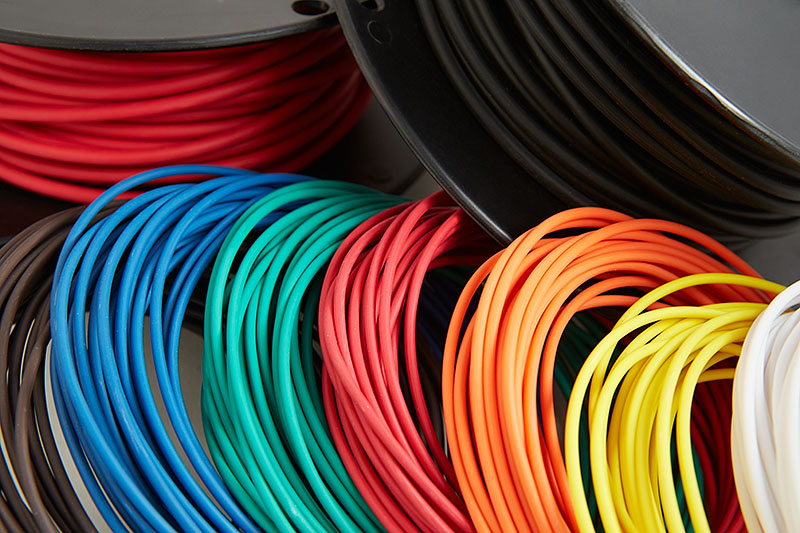
For automotive wiring, there are three typical wire types that are used: SXL, GXL, and TXL. They have many of the same features, including high temperature ratings, great flexibility and cross-linked polyethylene insulation. The main difference between them is insulation wall thickness. SXL is standard thickness, GXL is thin wall, and TXL is extra-thin wall.
SXL
SXL wire is recommended for use in high temperature environments where high heat resistance is required as per SAE J-1128. SXL wire is frequently found in engine compartments, trucks, tractors, boats, buses, and general applications where high durability coupled with high heat resistance is a requirement.
GXL
GXL wire is recommended for use in high temperature environments where high heat resistance is required as per SAE J-1128. GXL wire is frequently found in engine compartments, trucks, tractors, boats, buses, and general applications where high durability coupled with high heat resistance is a requirement.
TXL
TXL Wire is recommended where high temperature resistance and small overall diameter are necessary. It is found in many automotive interiors (instrument panels, interiors, etc.) TXL Wire is frequently found in cars, trucks, tractors, boats, buses, and general applications where high durability coupled with high heat resistance is a requirement.
After researching, I chose to use GXL wire for this project due to it being the most commonly used and available automotive wire. More specifically, I wanted to use 18 AWG GXL wire for the switches and 10 AWG GXL wire for all of the accessory wiring to accommodate any high amperage devices. However, the overall outside diameter of 10 AWG GXL is is too big to accommodate the cable seals. Therefore, I chose to use TXL 10 AWG wire, which has Extra-Thin Wall insulation and a smaller outside diameter to accommodate the cable seals.
In the end, I purchased 18 AWG GXL wire for the switches and 10 AWG TXL wire for the accessories.
The 18 AWG GXL wire is readily available at Wire Barn, Waytek Wire, or Maney Wire as well as many other retailers.
The 10 AWG TXL wire is more difficult to find. I ended up buying it from Maney Wire, but it’s also available in 250′ rolls from Waytek Wire.
Welding Wire
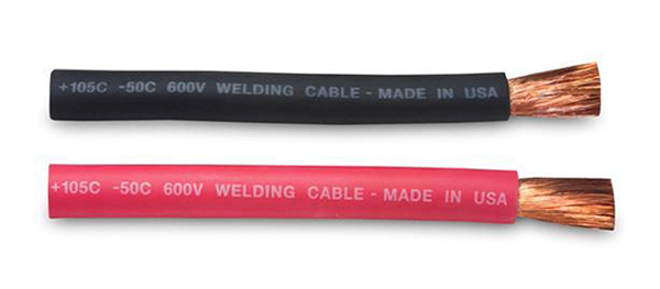
To connect the main power and ground sources between your battery and the Bussmann RTMR, 4 AWG welding wire is a good choice.
Parts used in this tutorial:
When making your parts purchase, you may want to buy various other wire gauges to accommodate your accessories. When doing so, only red and black would be necessary.
There are several ways to connect accessories to the Bussmann RTMR. The simplest option is to directly connect each accessory to the enclosure. However, this is restrictive and inconvenient, especially if you need to remove the RTMR or attach additional accessories in the future. I chose to use Metri-Pack connectors for several reasons:
The various sealed connectors available start on page 84 in the Metri-Pack catalog at Delphi, but this family of connectors does not have a mate for every connector. I’m not going to go into great detail here. If you want to learn more, check out www.metripack.com.
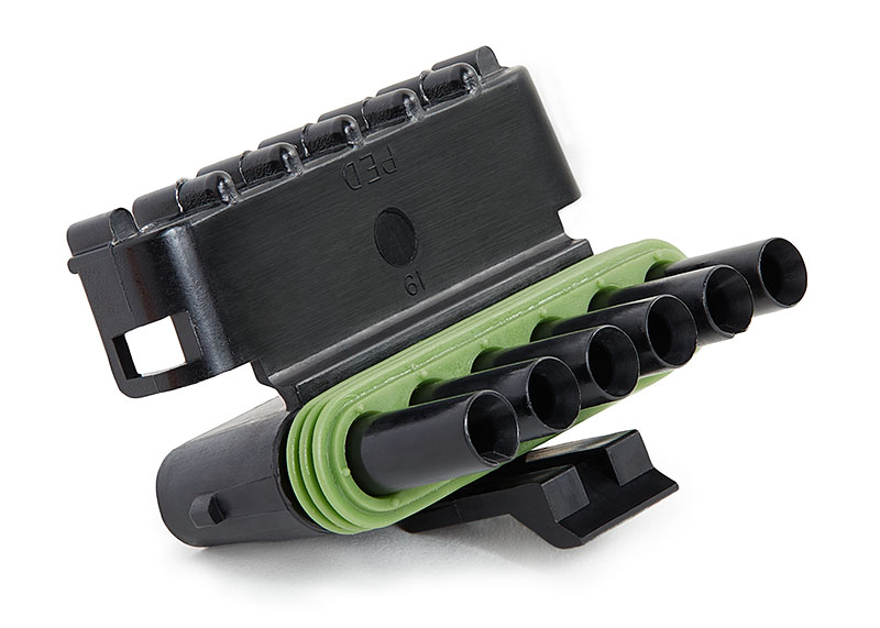
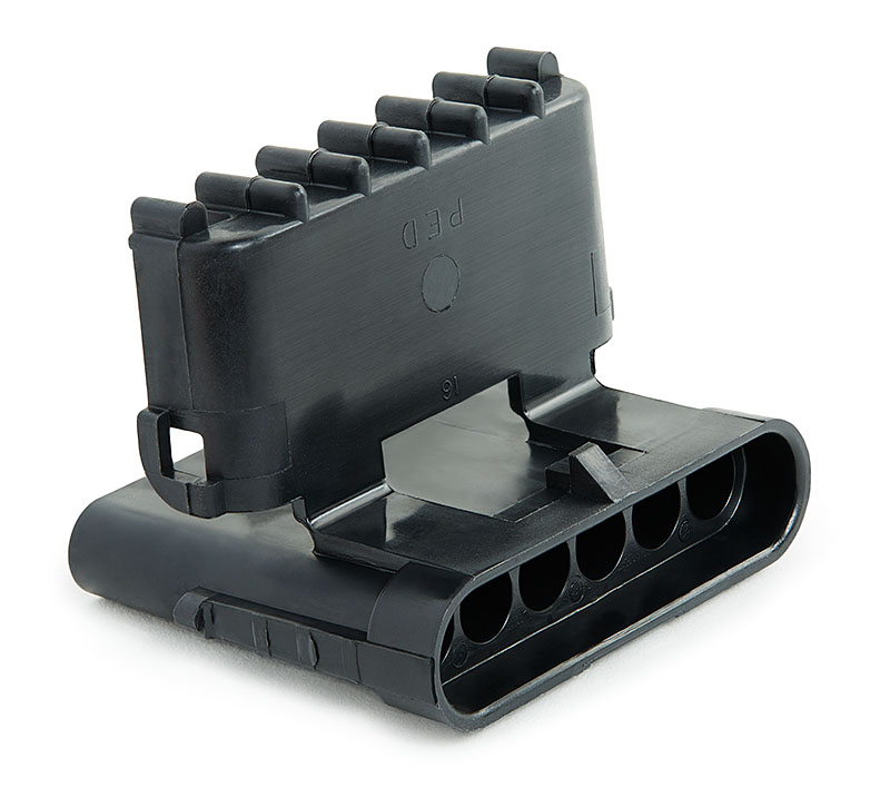
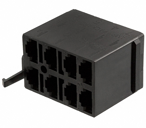
I used the two-way Metri-Pack 280 Series connector. There are three components to this connector:
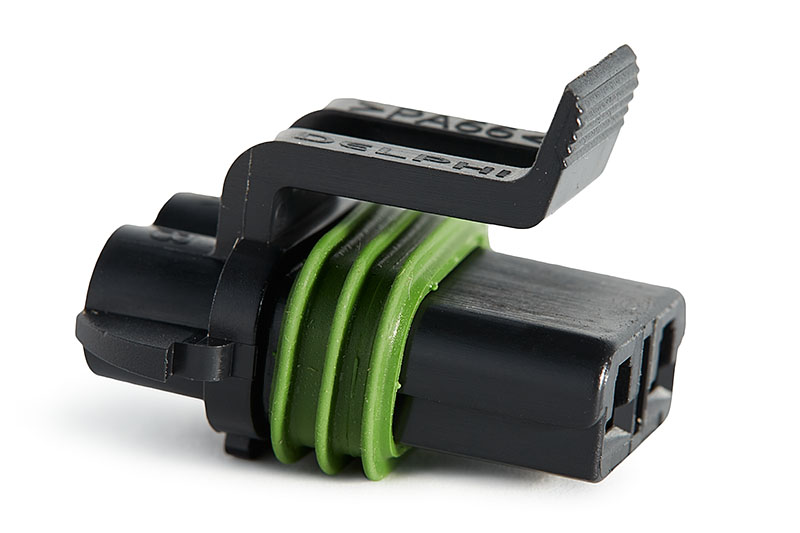
Female Connector Assembly: 15300027
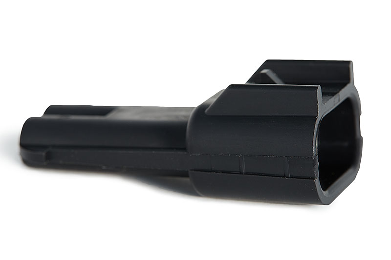
Male Connector Assembly: 15300002
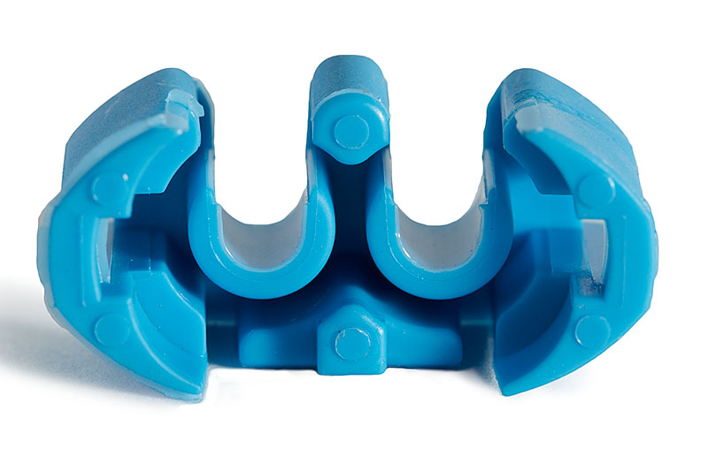
Terminal Position Assurance clip (2 required per connection, 1 each for male and female connectors): 15300014
Parts used in this tutorial:
Similarly to using Metri-Pack connectors for all of the accessories, I wanted a convenient way to disassemble the wiring harness to the switches. This harness will be made up of six 18 gauge wires, one for each switch and then a common ground. Unfortunately, there isn’t a six-way mating pair of connectors within the Metri-Pack family. Therefore, I used Weather-Pack sealed connectors. For more specific information regarding Weather-Pack connectors, visit www.weatherpack.com or the Weather-Pack catalog from Delphi.
There are two components to this six-way connector:
Female Assembly: 12015799
Male Assembly: 12010975
Parts used in this tutorial:
The switches most typically used are V-Series sealed rocker switches made by Carling Technologies. Within the V-Series line, typical choices are Contura II & III, Contura V, and Contura X. When shopping for switches, you’re are able to choose the following charactieristics:
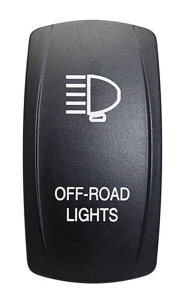
This allows great personalization to your project.
Parts used in this tutorial:
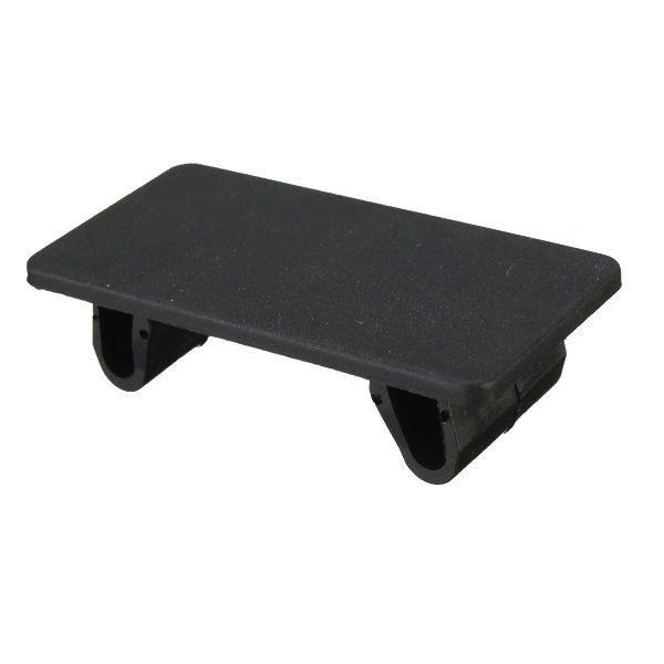
Since the Bussmann RTMR has five relays, I plan to connect five switches, but the panel I’m using accommodates six. Therefore, I purchased a switch blank to fill in the sixth position.
Parts used in this tutorial:
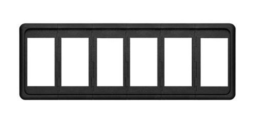
A switch panel or holder to mount the switches in your vehicle is necessary. There are several sizes to consider depending on how many switches you want clustered together. I’m installing five switches, so the six-position switch holder fits my needs. With this switch holder, I plan to install in the the overhead console sunglass holder.
If don’t want the switches in the overhead console or it won’t accommodate the switches, you’ll need to find a location that best fits your vehicle.
If you have a Toyota Tacoma, then another option is a panel to mount the switches in the space just forward of the shifter. Iggycorp makes a great panel to fit this location that accommodates six switches, which can be purchased here.
Parts used in this tutorial:
When wiring switches, there are several ways to do so. A very simple way is to directly wire to the rear terminals, but the problem with this method is that if you ever need to remove the switch panel, then it’s not a simple procedure. You would have to disconnect all wires and try to remember where each one went. Therefore, other alternatives are to use switch backs or some other sort of connector.
Rear terminal housings, commonly known as switch backs, are very popular and easy to use. They’re basically a mating part that attaches to the back of the switch. Your wiring connects to the terminal housing, which then plugs into the switch. If you need to remove the switch panel, then all you do is unplug the switch backs. The other neat thing is that they come in a variety colors to help you organize your installation.
As versatile as switch backs are, I did not use them, because there was not enough space in the overhead console sunglass holder to accept the increased depth needed.
Parts used in this tutorial:
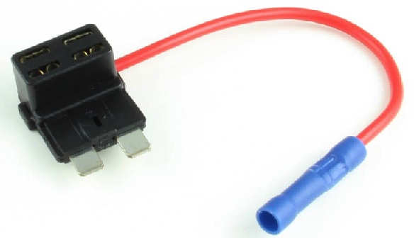
To supply power to your switches, we will tap into the under-dash fuse panel with a fuse tap.
Parts used in this tutorial:
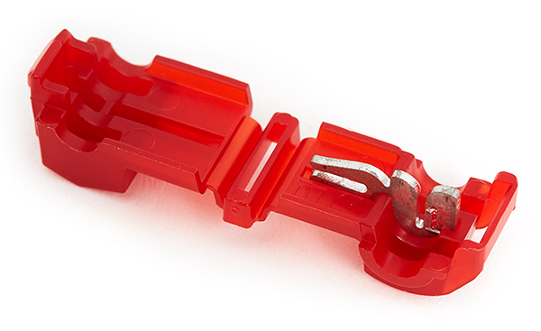
To provide power and grounds to the lower independent LED of the switches, we will be tapping into the vehicles dash light dimmer circuit. In order to do so, this will require splicing into the OEM wiring harness.
Parts used in this tutorial:
The one downside to using switch backs is that you need to have ample space behind the switches. So installing a switch panel in the overhead console sunglass holder, such as in my project, prohibits the use of switch backs. Therefore, I chose to use Mini-Fit Jr. connectors made by Molex. This line of connectors can host up to 24 connections at 9 amps. This project needed 9 wires to connect to the switch panel, which I’ll explain later, so I used 10-position connectors.

Male plug connectors (Molex part #39-01-3103) can be purchased at Mouser.
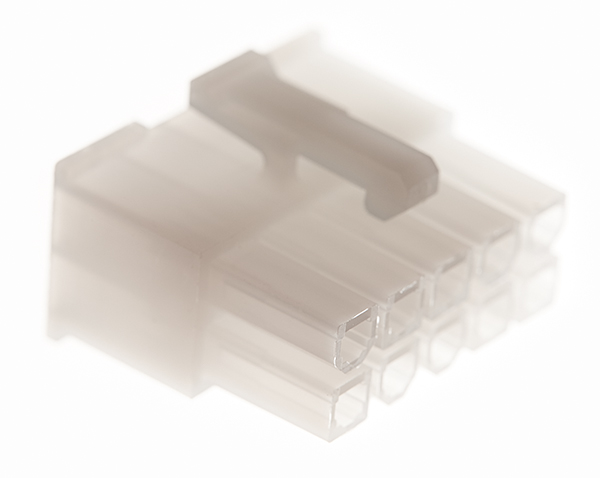
Female receptacle connectors (Molex part #39-01-2100) can be purchased at Mouser.
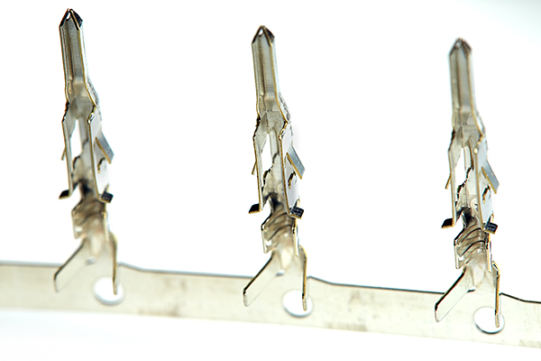
Male pin terminals (Molex part #39-00-0040) can be purchased at Mouser.
Female socket terminals (Molex part #39-00-0038) can be purchased at Mouser.
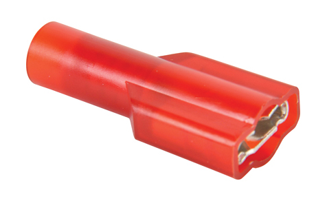
Insulated female quick disconnects are used to connect to the terminals on the back of the switches or switch backs. They need to be insulated, as shown. Otherwise, you severely risk an electrical hazard. Wire size to the switches will be 18 AWG, so choose the correctly sized connector, 22-18 AWG.
Parts used in this tutorial:
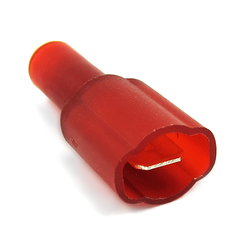
Insulated male quick disconnects are used in conjunction with wire splice connectors to tap into the vehicles dash lighting dimmer circuit. Wire size to the switches will be 18 AWG, so choose the correctly sized connector, 22-18 AWG.
Parts used in this tutorial:
The Bussmann RTMR accepts ATM Mini fuses and ATM Mini fuse circuit breakers with a 280 footprint (2.8mm). It’s a personal choice to use fuses or circuit breakers. Either will work just fine. However, if you choose to use circuit breakers, you need to purchase the RTMR with the taller cover to accommodate them. 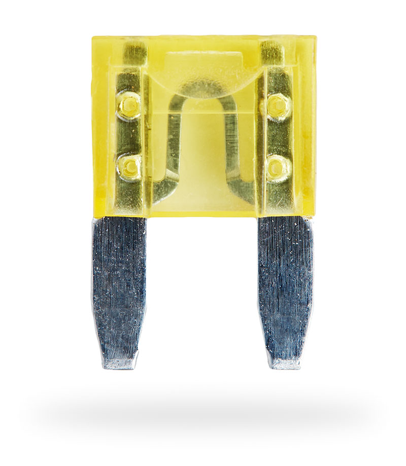
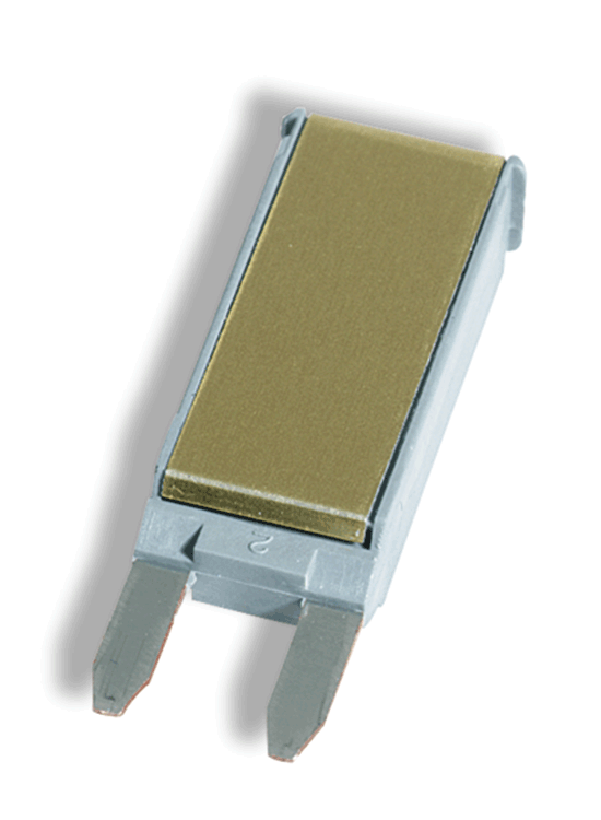
As far as sizing goes, this is determined by the gauge of wire used.
18 AWG – 7 amps
16 AWG – 10 amps
14 AWG – 15 amps
12 AWG – 20 amps
10 AWG – 30 Amps
Parts used in this tutorial:
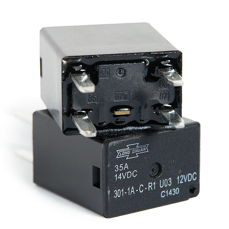
Depending on which version of RTMR you’re using, you need to use either ISO 280 Micro or Mini automotive relays, which have 2.8mm terminals and mate with the Metri-Pack female terminals used in the RTMR. A basic rule is if the enclosure you’ve chosen accommodates five relays, then you’ll need to buy Micro relays. Otherwise, if it only holds three, then you’ll need to purchase Mini relays. As for the RTMR enclosure I’m using in this tutorial, you want to buy ISO 280 Micro relays.
In Part 4, Wiring & Schematics, I’ll explain in more detail how a relay works and how to connect an accessory to it. For now, just understand that there are two types of relays:
The SPST relays are four-pin and the SPDT relays are five-pin. SPST relays are used to control a single circuit. When the relay is in the off position, the circuit is off. When the relay is on, the circuit is on. SPDT relays are used to control two circuits. When the relay is in the off position, one circuit is on and the other is off. When the relay is in the on position, the circuits are reversed. The first is off and the second is on.
I’m using 4-pin SPST relays in this tutorial. If you have a need for 5-pin SPDT relays, then you’ll need to make your own adjustments with regards to wiring. But it’s really easy and you’ll know how to do this after completing this tutorial. I’ll get into more detail regarding this in Part 4, Wiring & Schematics.
The relays I’ve chosen to use are made by Song Chuan and have a standard naming convention to identify them. As an example, let’s use this part number: 301-1A-C-R1

Using the above chart for reference, let’s go in order from left to right.
Here’s the datasheet for these relays.
Parts used in this tutorial:
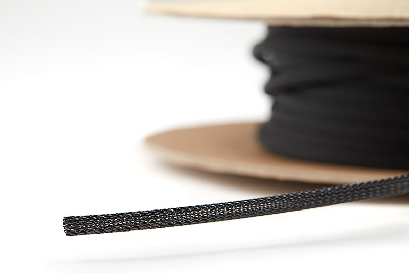
For the switch wiring harness, I’ll be using 1/4″ expandable sleeving wire loom.
Parts used in this tutorial:
Heat shrink is used to protect and bind wiring together. If you start researching heat shrink, you’ll find a dizzying array of options. With the Bussmann RTMR enclosure and Metri-Pack connectors, the weatherproofing doesn’t come from the heat shrink but instead the silicone cable seals. Thus, adhesive-lined heat shrink isn’t required, but I ended up using it because the adhesive helps to hold wiring and braided sleeving in place.
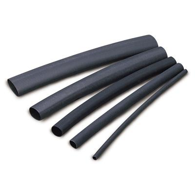
I used various sizes of heat shrink tubing. 3/8″ adhesive-lined, 1/2″ adhesive-lined, 3/4″ adhesive-lined, and 3/4″ clear.
Parts used in this tutorial:
There are many ways to mount the Bussmann RTMR. You can purchase one made by Bussmann specifically for the RTMR, but you might find it very limited. You can also make one yourself out of plexiglass, steel, or aluminum. Whatever you choose, the choice is yours.
The Bussmann mounting bracket, B028-7012-0-J, is probably the most affordable and can be purchased at Waytek Wire.
The following mounting bracket is made by a Tacoma World member by the name of Yotamac that perfectly fits in a Toyota Tacoma. He makes several sizes, with and without the custom laser cut-out. So even if you don’t have a Tacoma, you may be able to mount the bracket in your vehicle somewhere. You can contact him through his message post on the Tacoma World Forum or his user profile.

Parts used in this tutorial:
The Bussmann RTMR is configured with or without internal busses. Of the two that I recommend using, 15303-2-2-4 and 15303-5-2-4, both have an internal bus that is used to provide power to the fuses. This tutorial focuses on the RTMR that is configured with two internal busses, 15303-2-2-4.
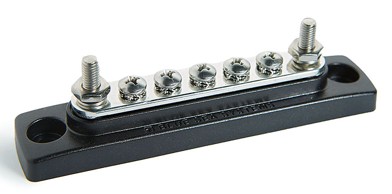
Even though the RTMR enclosures offer internal bussing, we still need to take care of the grounds for all accessories. I chose to use two external ground busbars. One is used for five accessories attached to the relays, and the other is used for five accessories attached to fuses. I’ll get into more detail later in Part 4 – Wiring & Schematics.
The following Blue Sea Systems 5 Gang Common 100A Mini Busbar is perfect for our needs. It has five #8-32 screw terminals to attach the accessory grounds and two #10-32 stud terminals to attach the busbar to your negative battery terminal with a larger gauge wire. It’s also rated at 100A, which closely matches the rating of the internal busses of the RTMR.
Parts used in this tutorial:
To connect your ground wires from your accessories to the ground busbars mentioned above, you’ll need heat-shrink ring terminals. You’ll also need another heat-shrink ring terminal to connect the ground for the switch LEDs. I’m using heat-shrink ring terminals to protect the wiring from corrosion. You can also use standard ring terminals with adhesive-lined heat shrink if that’s what you have available.
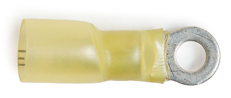
We need ten ring terminals for the accessory to ground busbars. These are 12-10 AWG with #8 hole. We will also need one 12-10 AWG with 1/4″ hole and another 12-10 AWG with 5/16″ hole.
We need one ring terminal for the 18 AWG ground wire for the switch LEDs. Therefore, you can buy 22-18 AWG, 1/4″ hole heat shrink ring terminals from Waytek Wire, Del City, or Amazon.
Parts used in this tutorial:
To protect the Bussmann RTMR, you will need to install a fuse or circuit breaker. The choice is up to you and tends to be a personal preference.

I used a Blue Sea ANL Fuse Holder with Insulating Cover 30- 300A, Part # 5005.
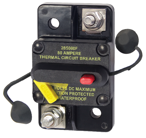
The other option is a circuit breaker: Blue Sea 285 Series Surface Mount 80A
Parts used in this tutorial:
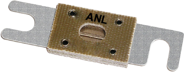
If you choose to use an ANL Fuse Holder such as I did instead of a circuit breaker, then you need to buy 80A ANL fuses.
Parts used in this tutorial:
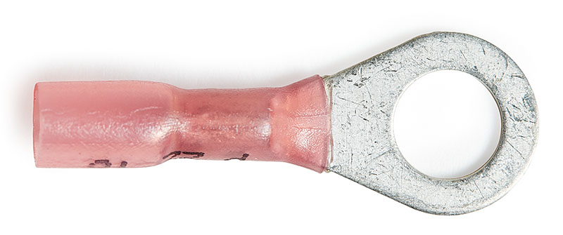
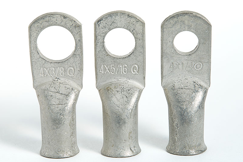
As mentioned earlier, I chose 4 AWG welding wire to connect the Bussmann RTMR to the battery positive and ground. For the studs on the Bussmann RTMR, you’ll need lugs with a 5/16″ hole. The studs on the Blue Sea busbars, are #10-32, so the smallest available lug for 4 AWG that I could find was 1/4″ hole. Depending on your specific setup, you may need to get lugs with a 3/8″ hole or even 1/2″ hole.
Parts used in this tutorial:
This article has outlined all of the necessary parts required to build an enclosure. To summarize, I’ve included the following list with part numbers, links to where each part can be purchased, and quantities needed. When ordering, keep in mind that many parts require a minimum number to order. This isn’t a bad thing, because mistakes will be made. Therefore, it’s beneficial to have extras available.
In the next part, Part 3 – Tools and Techniques, I’ll show you the tools needed to complete this project as well as the basic technique of crimping terminals.